


Advantech BB-422LCOR
RS-232 to RS-422 Converter DB25F to DB25M
 Properties
 Description
 Further Information
 Similar products
 Print this page
 Request Price
 show my notes
 PDF
PDF
 Properties
 Description
 Further Information
 PDF
PDF
- Converts unbalanced RS-232 signals to balanced RS-422 signals
- TD and RD LED data traffic indicators
- Data rates up to 90 kbps
- Extends RS-232 signals up to 1200 meters (4000 feet)
- RS-422 driver can drive ten RS-422 receivers in parallel
- Ten receivers can be connected to any one driver for use in multi-drop systems
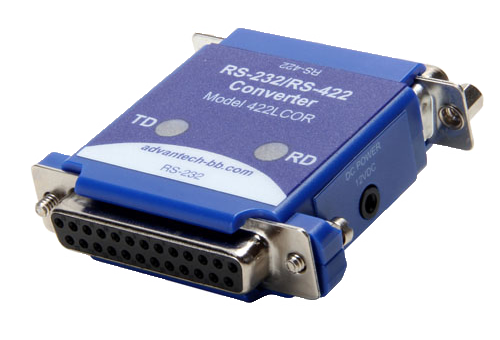
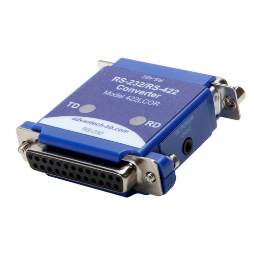
Model 422LCOR, non-isolated RS-232 to RS-422 converter, converts unbalanced RS-232 signals to balanced voltage digital interface to allow communications of 90K bits per second on cable lengths of 1200 meters (4000 feet). Ten receivers can be connected to any one driver for use in multi-drop systems.
The RS-232 port is a female DB25 connector with pins 2 (TD input) and 3 (RD output) supported. Protective Ground (pin 1) and Signal Ground (pin 7) are also connected. The RS-422 port is a male DB25 connector with Send Data outputs on pins 2 and 14, and Receive Data inputs on pins 5 and 17. Protective Ground (pin 1) and Signal Ground (pin 7) are connected through to the RS-232 connector.
Interconnection of the converter with another RS-422 device:
The polarity of the two RS-422 lines must be correct. With no data being sent the RS-232 line should be negative and the RS-422 A terminal should be negative with respect to the B terminal.
The wire recommended in the RS-422 Standard is number 24 AWG copper conductor, twisted-pair telephone cable with a shunt capacitance of 16 pF per foot.
For long runs and/or high data rates it is recommended that the wires be terminated with a resistor at the receive end. The twisted pair usually used has an impedance of about 100 Ohms, therefore a 100 Ohm resistor is normally used for termination. The RS-422 side of the converter requires more power as the transmission line is increased and termination resistor value is reduced, therefore it may be necessary to use a termination resistor that is larger than 100 Ohms.
The RS-422 driver has the ability to drive ten RS-422 receivers connected in parallel. A system of multiple receivers may require some experimentation with location and size of termination resistors, line lengths, grounding, etc.
The RS-422 Standard recommends that Protective Ground (pin 1) be connected to a good green wire ground. This may be already connected in your RS-232 equipment. Protective Ground and Signal Ground should be connected to each other using a 100 Ohm 1/2 Watt resistor at one end only. If a shielded twisted pair is used ,the shield be connected to Protective Ground.
SPECIFICATIONS
| TECHNOLOGY | |
| Data Rate | Up to 90 kbps baud |
| Connectors RS-232: | RS-232: DB25 Female RS-422: DB25 Male |
| Signals | TD, RD |
| Power Requirement | 12 VDC @ 100 mA, external power source |
| REGULATORY APPROVALS | |
| FCC, CE | |
| Directives | 2014/30/EU - Electromagnetic Compatibility Directive (ECD) 2011-65/EU - Reduction of Hazardous Substances Directive (RoHS) 2012/19/EU - Waste Electrical and Electronic Equipment (WEEE) |
| Standards | EN 55032:2015 Class B - Electromagnetic Compatibility of Multimedia Equipment - Emission Requirments EN 55024:2010 - Information Technology Equipment - Immuity Characteristics - Limits and Methods of Measurement EN 61000-6-3:2007+A1:2011 - Generic Emission Standard for Residential, Commercial and Light-industrial Environments (Class B) EN 61000-6-2:2005 - Generic Immunity Standard for Industrial Environments |
| MEANTIME BEFORE FAILURE (MTBF) | |
| MTBF | 8888099 hours |
| MTBF Calc. Method | MIL 217F using Parts Count Reliability Prediction Method |
 Customers who viewed this item also viewed